Building a workshop to build the car in

As the project has reached a point where it going to need a place to be built in, we decided to build a modular workshop now. The design below was drawn up first. The idea was that it can be spit

The Cad drawing of the workshop

The Cad drawing of the workshop with the roadster in it

down into four sections to be transported to a new site Planning on moving to a better site in the next couple of years. The design is built around a freestanding central truss across the middle of the workshop to which the four section of the workshop are bolted. Each section of the workshop includes a floor section side and end wall and roof (when the sections are moved these will have to be supported with braces).

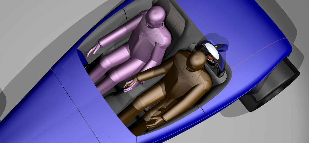
It will be another month or so before the interior of the workshop is completed so a little longer before we get back to the roadster. Looking forward to building up the basic frame and seating to test that it is comfortable before designing to much more, may be the steering wheel mounting need to be designed first. The car has got to be drive-able, so we wanted to do some full scale testing to be sure…..hence the workshop.

(more…)

The interior….the seats

Firstly sorry for the lack of updates in the last months, we have been building as extension of our development workshop in Florida, adding an extra 800 sq feet for chassis building and it has taken all our spare time to get the new concrete floor in.

Taking a break as it is recommended that you allow 28 days for the concrete to cure and evaporate water contained in the concrete before sealing, so a little time to progress the roadster design.Interior-1

The seat design– the idea behind the seat design is to produce a fixed position seat and use a movable pedal box and steering column to allow for different driver height and size. To be able to made the seat look like an integral part of the car design, most of the seat will be molded carbon fiber cover in leather. In effect a hard surface to allow good fitting to the painted panels. Only the seat center will be padded again with a hard edge to give a good looking fit. (more…)

The interior-checking humans can fit in the car

Interior design_20160204_151911

To be able to model the interior of the car firstly we needed a model of a human, using Grab Cad . (check out this site for downloadable models- links to my downloadable models). We downloaded a model of a man (could be a woman…) loaded into power-shape cad modeller and checked the height of the model man. It was 6 foot 3″ so we scaled it to both 5foot 7″ and 6foot.

Grabcad model of a man

Grabcad model of a man in the new sitting position

(more…)

Working on the Hood Assembly

Over the Christmas break, decided to look at the hood assembly design. At the moment the body-shell skin is a rough patchwork of surfaces. By this method you can more quickly come up with a basic shapes that you want without all the time needed to ensure that the surfaces are joined and flow together perfectly. Making class A surfaces (perfect surfaces) as you are trying ideas would be very slow and make it more tempting to keep a shapes as they took so long to make.

37 Willy's in red with hdr background

37-Willy's-port-containers-hdri This is a “38 Willy’s” style pickup model with the body skin surfaces redrawing to a class A standard. Rendered using Maxwell Software with an spherical Hdri background which also creates the shadows and reflections on the model.

(more…)

The Roll bar idea


As we are still looking into new dynamic software to check the suspension and ride height system out, still favoring Solid Works premium, but it’s expensive and still do not like the surface modeling side of the package. Therefore would not be using it to model with, so working with the demo to evaluate it at the moment.

Roll-bar-designRoll-bar-design-2
Therefore to keep the design work going forward decided to design the roll bar. While looking at the roll bar and how it will be mounted to the chassis, I decided to modify the main chassis rail removing the tail parts and extending the main rails. This has reduced the number of parts in the chassis and the main rails are now shorter and one straight piece. (more…)

Steering Racks

Back after a short break still have not tried the trial Solid works package to prove out the suspension design


Thinking about the next problems Steering racks

These are nice quality components that are high adjustable

Shows the Woodward Steering Rack front mount style in position on the chassis, the brackets and tubing still need some work as the hydraulic ram are in the same place. These steering racks are nice quality components that are high adjustable

Building cars with modern wide tires has it’s drawbacks. The wider the tire’s section the more caster is needed to get the steering to self center. This is compounded if there is a large scrub radius. The end result of all this is heavy steering with little feel. Therefore manual steering is not very effective, thus power steering is required. (more…)

Looking at design projects by others

espera-sbarro-eight-bridgestone-tiresThe students of ESPERA Sbarro Montbéliard built this: called the Sbarro Eight hot-rod concept.>click here and here for more info.

Sbarro is an auto school that teaches its students, the fine art of car design and car materials. Not sure that I’d want one, but it’s good to see something new and fresh built from the ground up start with a 3d model. It is a shame that only a school in France can inspire their student by allowing them to build something like this. It’s time for some of the American colleges to show their students talents as well as this…..

hotrod-concept_UVO5m_5965Another designer who’s work I have seen on the internet over the years is Tristan Hipps (more…)

Front Suspension System

215 front suspension_20150722_010511

Suspension with coil-overs in maximum ride height

215 front suspension_20150722_101347

At min ride height showing the swing arm movement

Working on the front suspension system forced some decisions on the design. Variable ride height with soft spring value at the high ride height and stiffer spring value at the lower ride height was add to the design spec. Air bags are the easy option but do not meet our spec, in fact they do the opposite as the spring value increases with ride height. The only way to increase ride height is to increase air pressure hence increase spring rate.
The only method possible is a mechanical system which changes the coil spring angle and the effective length. The design in the picture shown my first attempt using a swinging arm to mount the fix chassis end of the coil-overs to.
All the suspension mounting points are taken from the suspension analysis software and transferred to the Cad system. (more…)

Front Subframe Ideas

front-subframe-idea

Decided that the front suspension and engine mountings should be on a sub frame. This will enable different engine and suspension systems to be made and offered. Starting with the ultimate system with the Coyote engine and self adjusting ride height independent front suspension. Started with a basic tube setup as shown. (more…)

What is all this design work for

As I have not done any design work for the last two weeks I thought I’d post on what the point of all this design work.

The design shown is going to be produced in my home workshop, the main workshop is for production only. Production and one off design work do not mix, so firstly I am building a home workshop, I’ll post the design for the workshop soon. Then I will produce a wooden master to make molds from. This will be produced from the model using cut sections thought the model to produce bulkhead over which string will be added. The chassis will be laser cut and folded by a local fabrication shop. All the machined components will be machined in house but the machining could be outsourced.

The end result will be a complete driving car. All the stages of the design and build will be documented on this blog.

Idea for the Roadster Hood

Idea for the Roadster Hood and Roll bar

Think about changing to a Carbon fiber frame

The Main Chassis Rails

The main chassis rails have now been redesigned to include holes to plug weld and bulkheads to increase the torsional stiffness. the bulkhead are designed to be welded to the sheet though the slots shown. Then the inner cover plate will be plug welded to the outer rail

chassis rail 1

This shows the bulkhead inside the chassis rail

chassis rail 2

Shows the slots cut into the outer rail for the bulkheads to be welded into. All the holes will be cut using a laser cutting machine before the plate is folded.

chassis rail 3

Show the slots for the bulkheads

chassis rail 4

Shows the plug welding holes to weld the inner cover plate to the outer rail.

  Thinking about changing the rear structure to Carbon Fiber to reduce the weight and make the structure easier to make as it is becoming too complex to fabricate. This would entail adding overlapping onto the chassis rails to allow bonding and riveting.

Will work on the chassis rear legs next as the ends of the rails may need to change. Planing to unfold the chassis rails and produce a 2d dxf file of the chassis rail parts. These files can be send to the laser cutters from which they can produce the parts.

2015 Roadster Design Progression

215 Roadster underside

The Large fabricated side Rails will make the chassis very stiff without an interior full of bars. Plus they offer excellent side impact protection

215 rear view

Rear view, the rear chassis area is only conceptual at the moment. It may be too complicated.

rendering of 210 Roadster

This is a rendering for the basic chassis design for the 215 Roadster, showing the basic folded sheet construction

Decided to start work on the chassis design for the roadster using the body design shown in an earlier post. The idea of the chassis is to be a very stiff and minimal design. The chassis is also designed so that the body can be made in panels and bonded / bolted to it. As a concept idea the side chassis rails will be staying and will be developed further and will be the basis for the chassis frame.If you would like a more detail info subscribe to the 2015 Roadster Newsletter

This MailChimp shortcode is now deprecated. Please insert the new shortcode to display this form.

Why design using a 3d Cad System

Engine gearbox layout

A basic start point of design… The engine, Ford Coyote the transmission (in this case a Hewland trans-axle using 2d line drawing as no model available with custom drive support and the tires

In the past our cars were built as most do now, start with an idea then start building a chassis. Now everything is designed using 3d cad. Here’s why

  • It Makes your designs build-able

You can start with a model of the engine you want to use and a model of a man therefore ensuring that both will fit in the car

      • You can reuse sub-components from previous designs
  • Some components can be directly machined from the model
  • Produce high quality rendering (pictures) from the model  to show the customer.
  • Time-line of the project is easy to keep too.
  • Everyone working on the project knows what is expected as they have renderings and the model to refer too.
  • Sub contractors can have accurate 2d drawings of the parts required complete with note directly from the model reducing errors and rework.
  • Bad Styling or Design shows up sooner in the project.
  • Less desire to change the designs as you build, help to get the project finished
  • Forces you to cost the parts of the project earlier so changes to suit the budget can be made at the start.

The only negative is you will need to learn how to use the software, this takes time but even for one project It’s worth it. Or you pay someone like us to do it for you.

The end result will be the car will look and work better for it.

Interesting blogs I found on the net        Core7   thoughts about modern redesign of old styles and warfields     using Corvette c5 transmission 


Reduced ploy model of the Ford Coyote

The same model reduce file size

The same model as the last post with a reduced file size

To save buying the very expensive graphics card at this time, I reduced the poly (triangle) count on the model, this reduced the file size to the point where my existing graphics card can cope. In the future I will purchase a better one as my models are becoming more complex, therefore more graphic card memory capacity is required to rotate the model smoothly. But for now I can use what I have, plus I want to more research into graphics cards. Cad systems requirements are different to games requirement, direct x performance is important. The recommendations are for the workstation cards but they are much more costly than the Pc cards.

The file size reduction can be perform within many types of 3d Cad software, in this case I used Delcam Power-shape as I am using this to do the concept modeling

Further work on my 32 style Roadster

Model of Ford's Coyote Engine

Model of Ford’s Coyote Engine

Working on the 214 roadster, started it in 2014 hence the name. Decided that a small block Chevy is too old hat, so searched the internet for a model of Ford’s new Coyote engine. Finally purchased a very detailed mesh model (triangles), it looks wonderful. There is a but, the file is so large that it slows the screen refresh as you rotate the model.

Looking into the Nvidia Quadro M6000 graphic card. Visit the web page  , very large sticker shock may I’ll have to look lower down the range.

32 hi-boys

Having condemned all 32 hi-boy roadsters yesterday I received my copy of Hot Rod Magazine and there is another 32 hi boy featured click here to visit feature. This is a very nice redo of an old look. The DuVall screen is nice piece especially with the hardtop. The car has an interesting power plant,manual transmission and disc brakes which should make driving it more fun. Overall the car is beautifully crafted and the fit and finishes are exquisite. This is the only 32 hi-boy that has attracted my attention for a long time.

The BUT……… with all this skill, money and effort why not build something truly unique.

Updated 3 window Coupe

coupe 202 business card redcoupe 202 version  in red shopped twocoupe 202 version  in black shoppedcoupe 202 complete in blue 3

A few renderings from a Cad model of an updated 3 window coupe

Produced using Delcam’s Powershape 3d cad software

Hotrods style cars and there future

Over the last 20 years the age of the average hot rod owner has been going up, early style hot rods are now almost all owned by guy’s in their sixties and over. The younger guy’s are now building later model muscle cars

The usual reason for this is this was the type of cars they grew up with and they are recreating their youth……may be true.

I don’t fit this description, never did, I like the style of early hot rods but not the way they drive. I’ve built many cars over the years and been to the all the shows.

It must be time for something new, I don’t want to see another fender less 32 hi boy. I want to see modern interpretations of a 32 hi boy. Similar to the new Camero, Fiat 500 in their conception.

This is not so easy to build and needs to be completely designed in a Cad system first (rhino cad is not that expensive around $1,000). If you cannot use these software’s learn or use the service of guy’s like me, there are plenty of us around. Obviously a complete set of molds need to be made, this is less expensive than you might think to do. The internet is full of helpful videos. I have done it and will be doing so again.

I will post over time details about how to approach these type of projects.

Love to hear from anyone taking the same approach. May be we can move hot rodding forward………..